Electrical and Pneumatic Components
An overview of electrical and pnematic components. None of these will appear in the dedicated glossary given that this in itself is much like an electrical glossary.Broken up in two parts:
pneumatics
Electrical
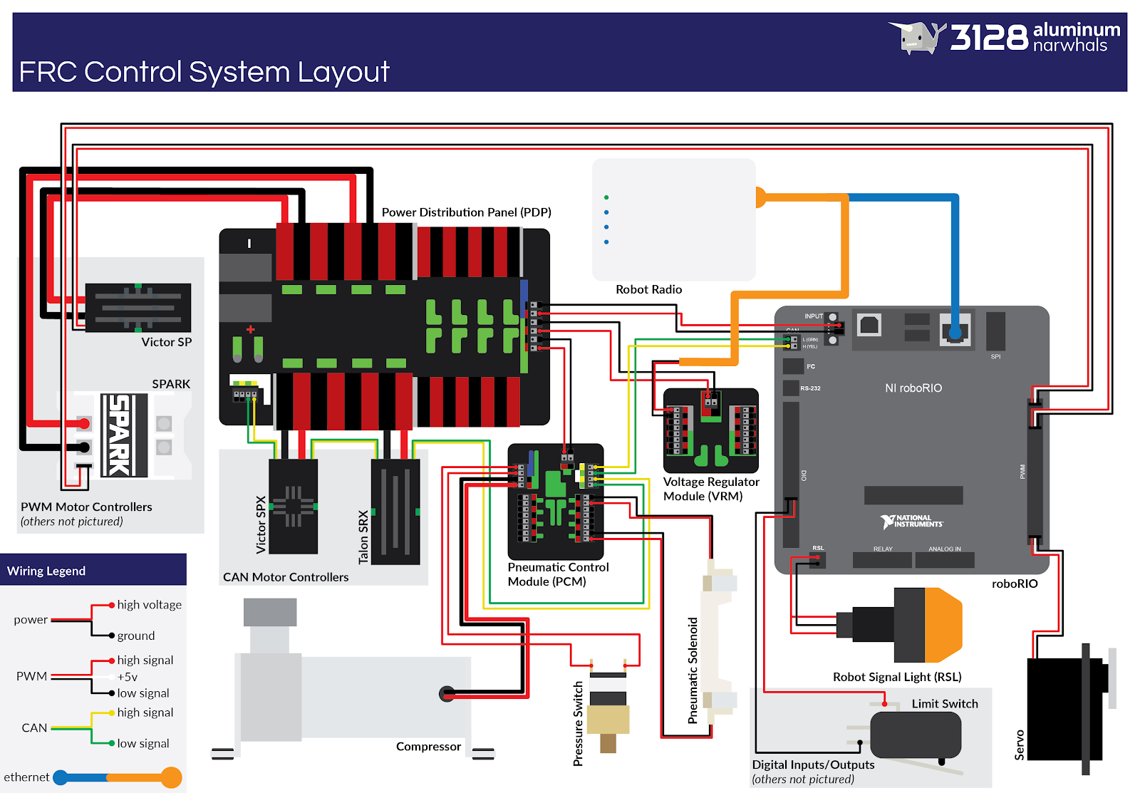
Electrical Diagram
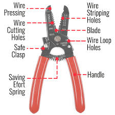
Wire Strippers
A wire stripper is a small, hand-held device used to strip the electrical insulation from electric wires.
It helps to cut off the plastic insulator around the wires so we are able to solder them and etc.
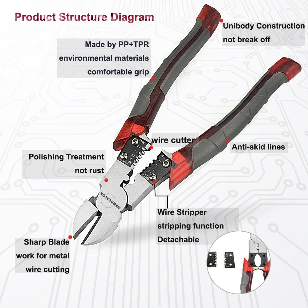
Wire Cutters
We use these to cut wires! (Big Surprise!)
These also work great for cutting zip ties, you don’t want to use scissors to cut them
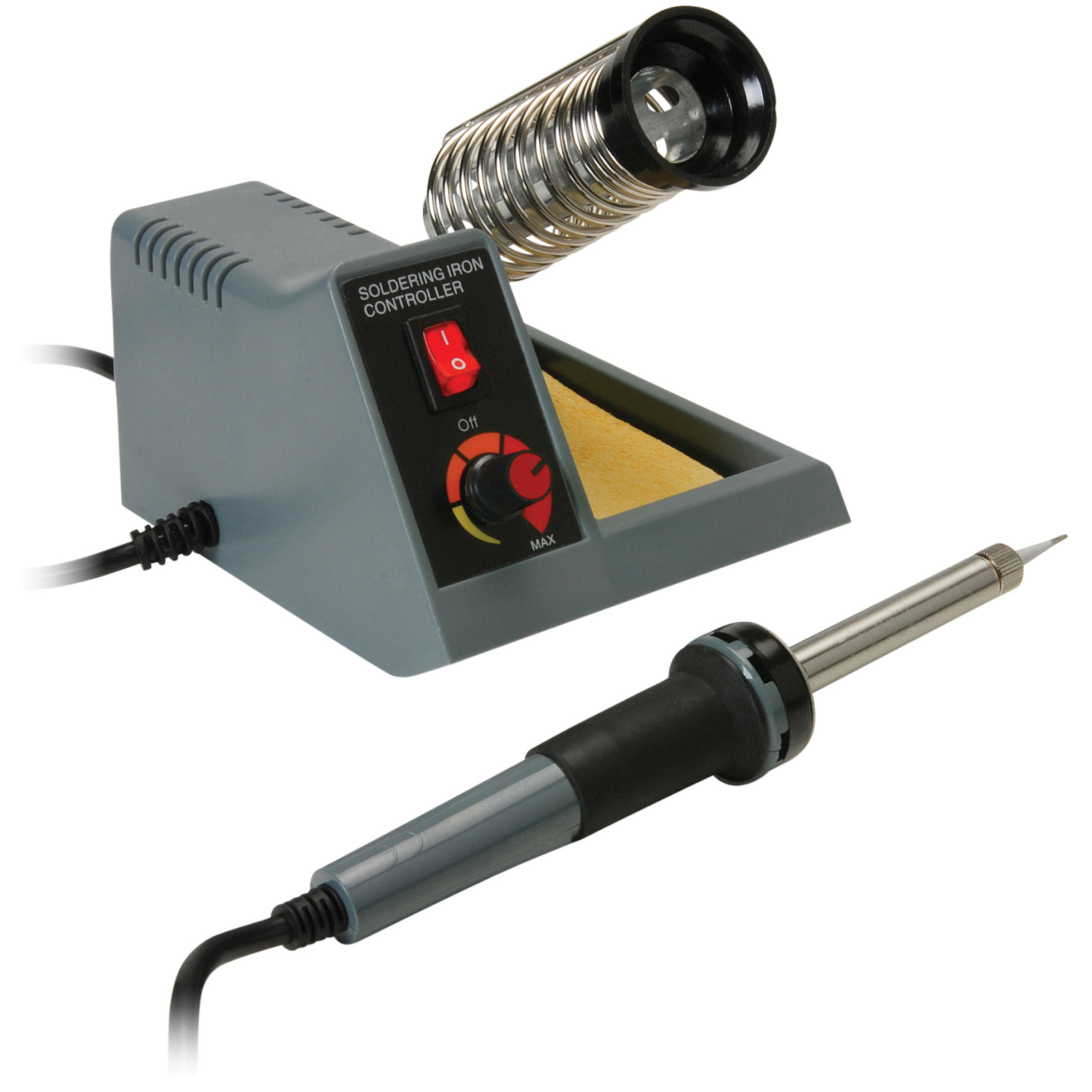
Soldering Iron
Soldering is a way to connect two wires
Solder melts and connects the two wires making a solid connection
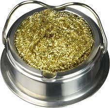
Wire sponges made of brass are used to clean the tip of the soldering iron
Shrink Tube/Heat Gun
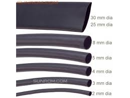
We use shrink tube to put over soldered wire bare connector to protect it against shocks and shorts
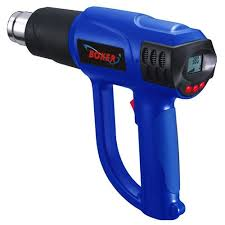
The heat gun heats up the shrink tube and it shrinks around the wire, securing the connection
Wago Tool
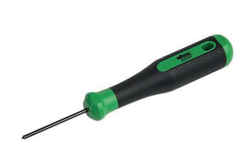
It opens the doorways on the PDP and allows the wire to enter
It presses down the entrance place for wires of the VRM, PDP, RoboRio, and main components
Also is very handy to use as a screwdriver on the RoboRio and other components
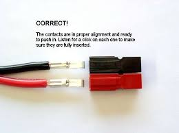
Anderson Connectors
We use these as the main connection points, think soldering, but much better
These connect to the motors, the PDP, etc.
Used for larger gauge wires
Has a specific tool to attach connector, the outer shells are the plastic black and red pieces, the actual connector is metal (see bottom right)

Ferrule Connectors
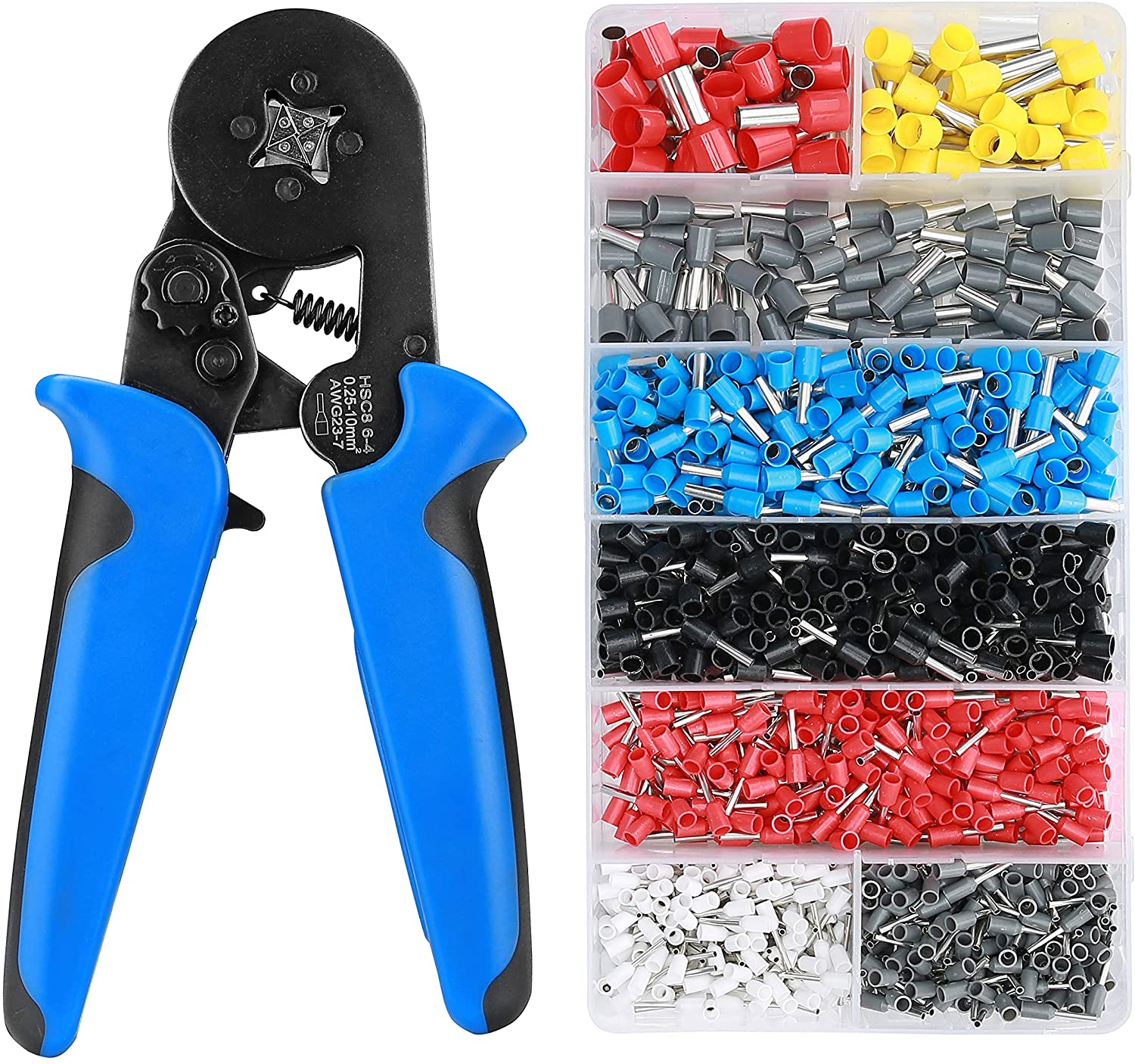
Different connector size for different gauges of wire
Used to connect to ports such as PDP and VRM
Definitely use on competition bots to prevent loose wires

Power Wire (Black + Red)
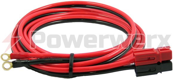
These would be connected to both the 12 volt battery and the PDP.
Red = positive
Black = negative
The wires will have an adaptor so it can connect to the battery.
Note
The battery will need an adaptor as well which you need to learn how to do but most of the batteries we have already have them
CAN Wire (Green + Yellow)
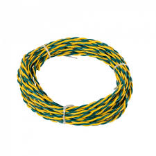
We use CAN wire to create a CAN bus loop between the drivetrain motors and any additional motors on the robot
CAN wire is also connected to the RoboRio, PDP, and PCM.
RoboRio
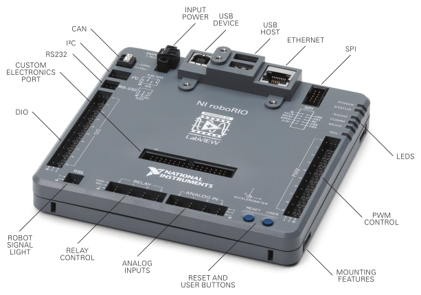
The RoboRio is the brain of the robot. It acts as the bridge between the code and body.
Tells every part of the robot what to do.
It needs a router though which is hooked up through the ethernet port.
Motors
What is a Drivetrain * A drivetrain is the system of motors, gears, and wheels that make up the robots drive system.
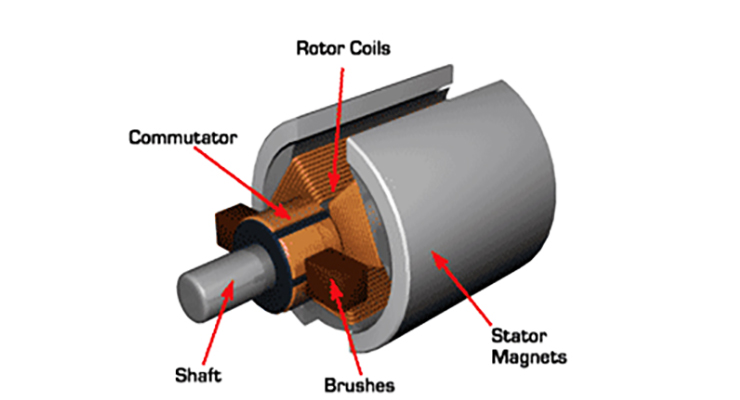
DC Brush Motors * A brushed DC motor uses a configuration of wound wire coils, the armature, acting as a two-pole electromagnet.
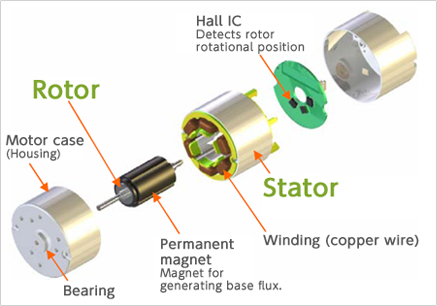
Brushless Motors * A brushless motor utilizes a permanent magnet as its external rotor.
Note
Make sure to label the motors so it makes it easier for programmers and yourself to identify the trouble motor
Motor Controllers
Connects motor to rest of robot
Delivers instructions to motors derived from RoboRio and other sources
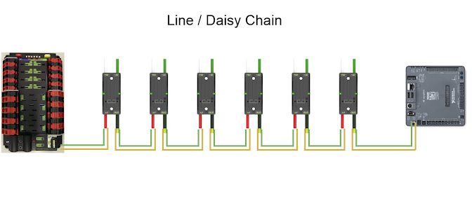
All controllers are connected by CAN wire
CAN wire connects them to RoboRio
Sole module connecting to motors
Connect to PDP
Limit Switch
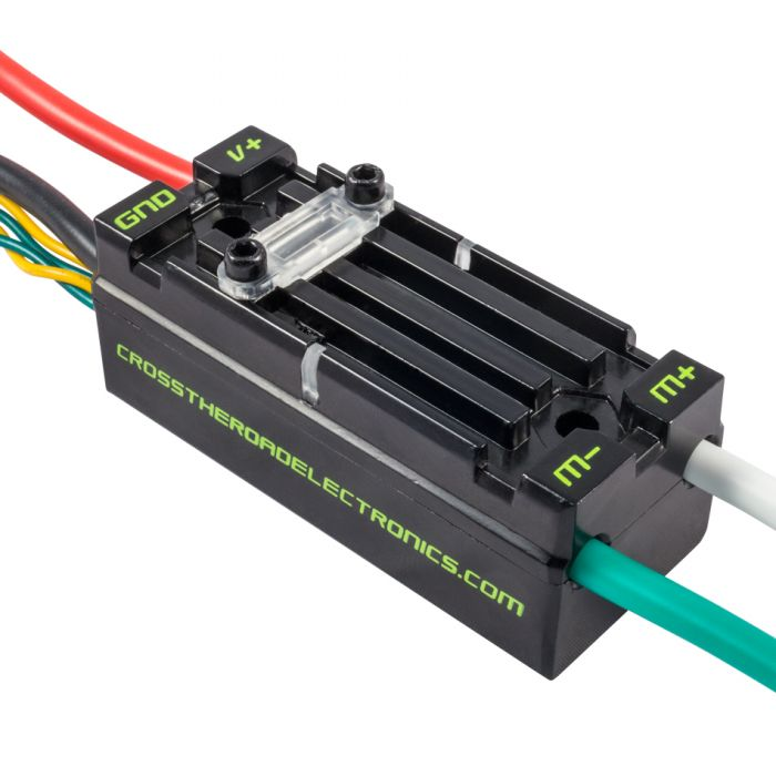
Works as a mechanical brake for a system on the robot
Activated by an object pushing against the switch arm
This ties into its two states: whether or not there is connectivity across the circuit
Senses a single position of a moving part of the robot
Prevents movement from exceeding a certain point
Plugs into DIO

Batteries
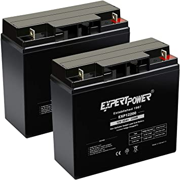
Batteries will need an adaptor in order for it to be able to charged/hooked up to the robot.
We use 12 volt batteries.
RSL Signal Light
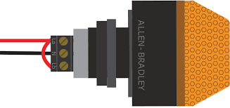
On every robot we have an RSL signal light
SUPER IMPORTANT, it tells us and everyone around that the robot is on and activated
Connects to the RoboRio next to RSL
Power Distribution Panel (PDP)
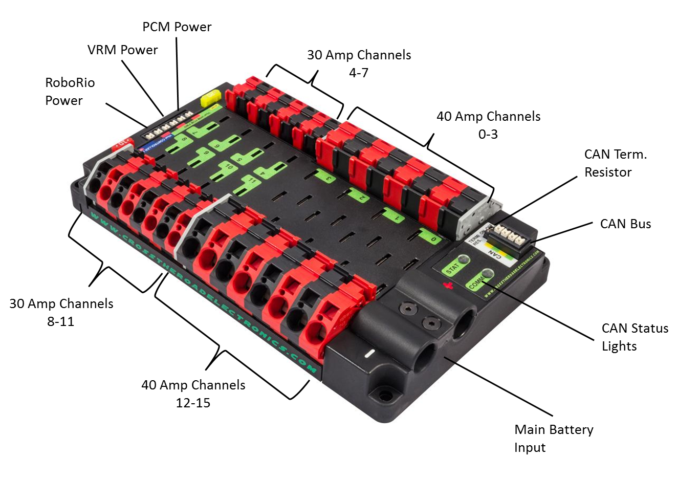
This component distributes the power
This is where the main battery plugs into
All major components and motors plug into the PDP
Fuses
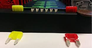
These little guys can often be forgotten (trust me), but the robot will not work without them
The fuses plug into the PDP, and determines exactly how much power goes through that output
There are 20, 30, and 40 amp fuses for all of the outputs, and 10 amp fuses for the power row of the PDP (as pictured)

Voltage Regulator Module (VRM)
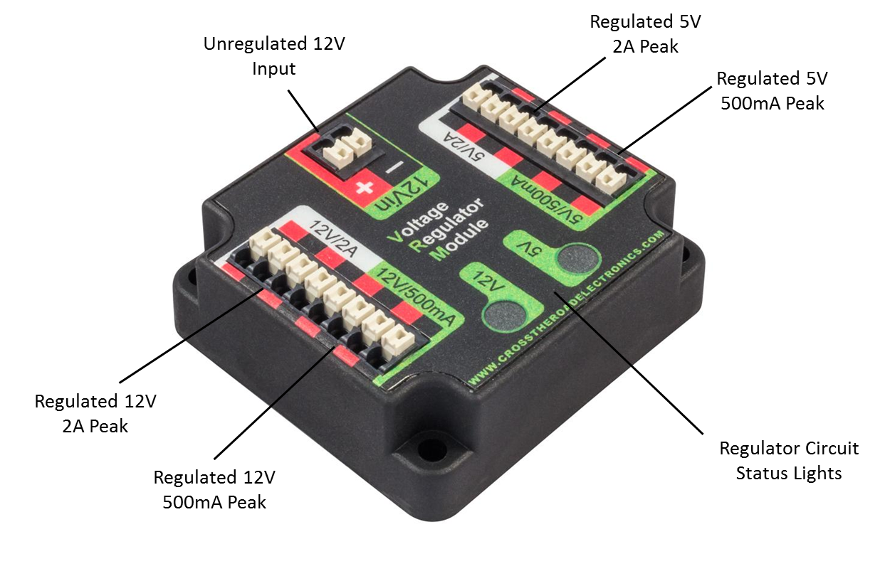
This component regulates the amount of voltage that goes through the wires
REMEMBER different components use different amounts of voltage, too much can cause a component to short out
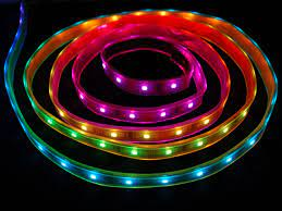
This is also used for any additional things you add to the robot (like LED lights :))
Circuit Breaker
A safety device for the robot, if it draws too much power it will automatically shut off!
This is basically the on/off switch for the robot
It connects directly to the battery, under the bolt
REMEMBER Place this in an accessible place on the robot
Circuit Breaker = On .. image:: images/EPComponents/oncb.png
Circuit Breaker = Off .. image:: images/EPComponents/offcb.png
Radio
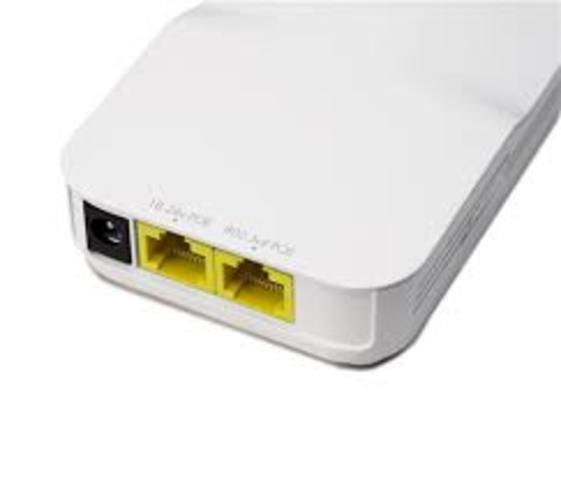
Gets hooked up to the RoboRio, pretty much the WiFi for the robot
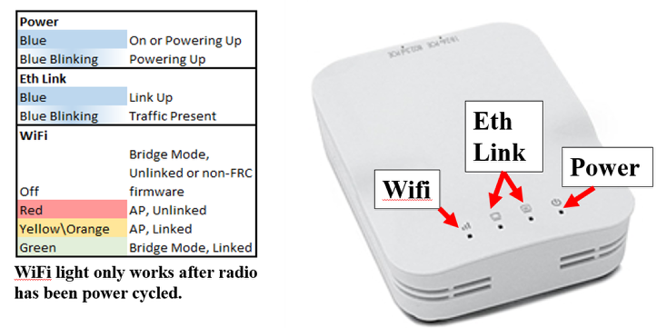
Where the ethernet cable connects to the robot
This section of the documentation documents setting them up (Programming) (ADD THE LINK– and do the same for rr)
Extra Stuff (LEDs, Circuits, etc.)
All extra circuits on your robot should connect to the VRM or the PDP
If you need to draw over 12V use the PDP
Make sure you plug it in to the correct voltage and amperage so you don’t end up (WHAT– PROGRAMMER HAS NO CLUE WHAT THIS IS SUPPOSED TO SAY)
Pneumatics
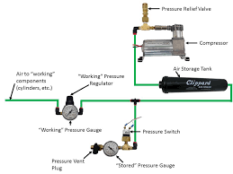
Pneumatics Diagram
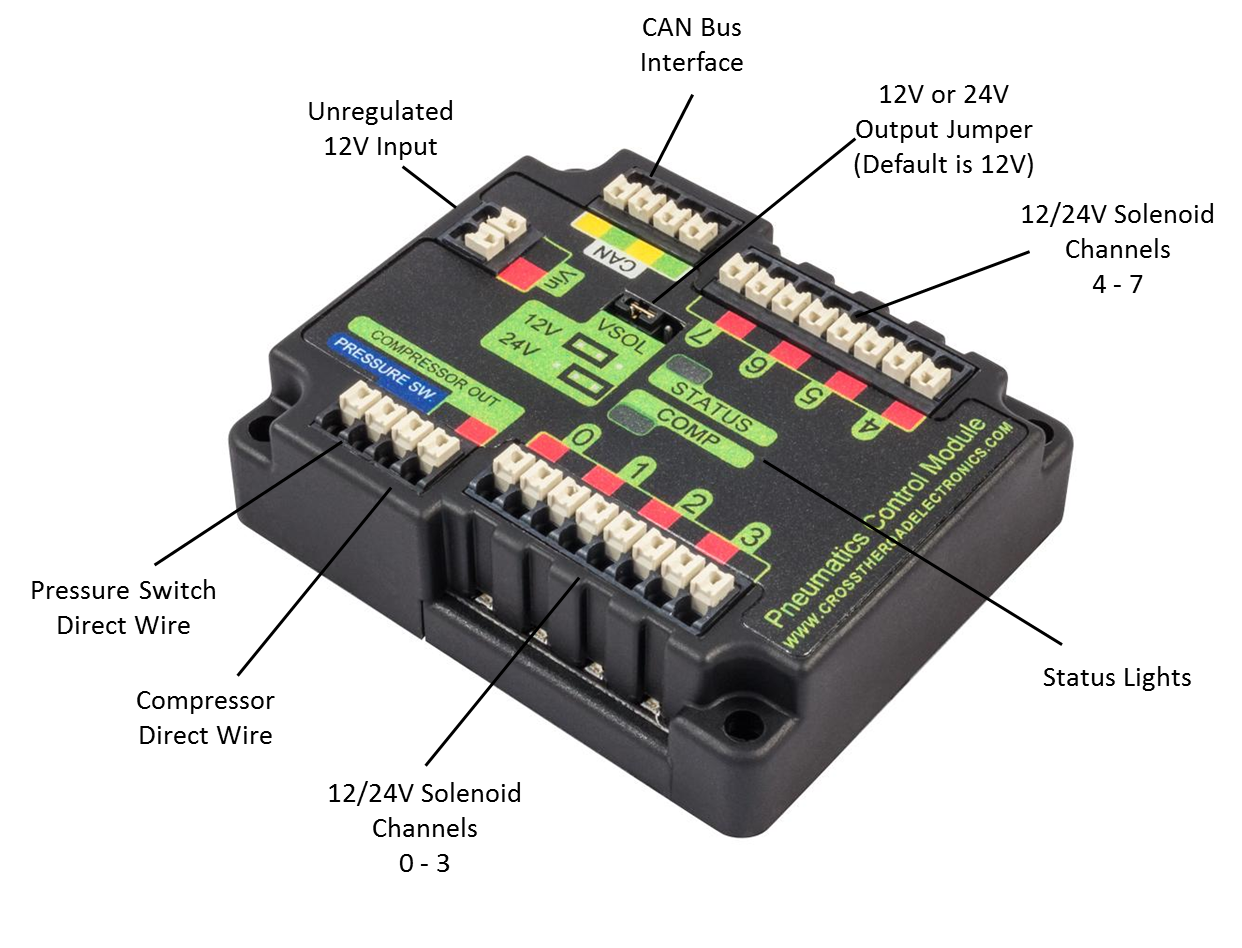
Pneumatics Control Module (PCM)
It’s a CAN-based device that provides complete control over the compressor and up to 8 solenoids per module.
It connects the pneumatic system to the electrical system
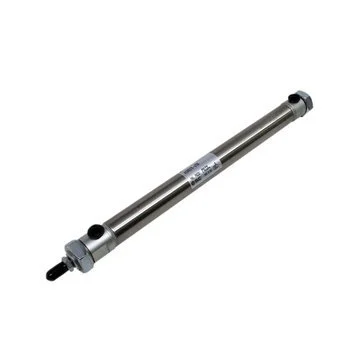
Pistons
A disk or short cylinder fitting closely within a tube in which it moves up and down against a liquid or gas.
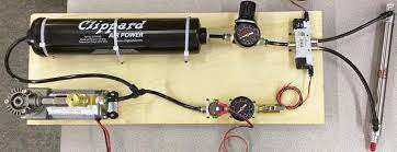
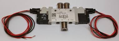
Solenoids
A solenoid is a type of electromagnet. In a solenoid valve the magnetic field created by a solenoid is used to switch a valve that
controls the flow of air in the pneumatic control system.
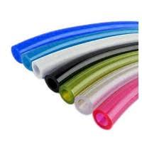
Tubing
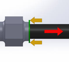
The tubing inserts into the connectors (first picture)
It’s where the air actually flows through
Make sure you have a secure connection or it may leak
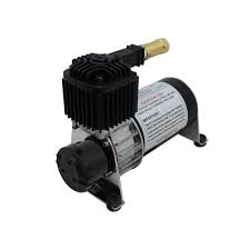
Compressor
Compresses the air for the rest of the pneumatics system
Connects directly to the PCM to ‘compressor out’
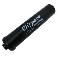
Air Tank
This stores the air used for the pneumatic system
Pneumatics tubing connects to each end.
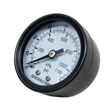
Pressure Gauge
Displays the current pressure in the pneumatic tubes
Should never go past 160
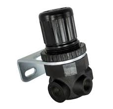
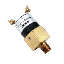
Pressure Switch
Wires are attached to the two screws and plug into the PCM (pressure sw.)
Connects to brass connector near the pressure gauge
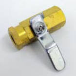
Pressure Relief Valve
A relief valve or pressure relief valve (PRV) is a type of safety valve used to limit the pressure in a system.
If something goes wrong with the pressure control system and the air pressure goes too high the valve will open to release it
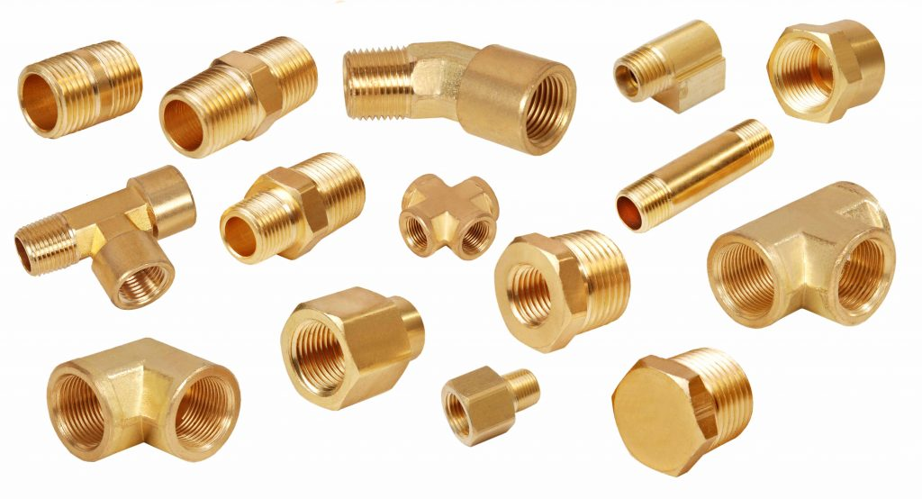
Brass Connectors
They come in a wide range of shapes and thread sizes to connect, adapt, or control any air flow.
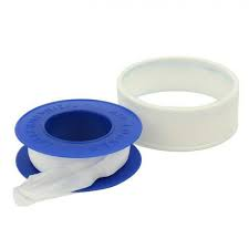
Pneumatics tape is used to seal the part of the brass that connects, it’s used to reduce leaks and needs to be on every connector.
T Brass Connectors
It’s a brass connector that can connect points in three ways.

Schematics (Natalie’s)
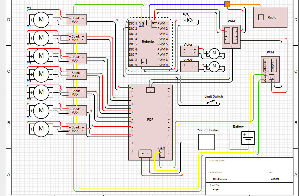
Schematics (Raul’s)

Inspector’s Checklist
Check the link out to know what inspectors look for in the robot.
That way you know what to watch out for when putting the components together.